PhotoRobot PINK 사용자 가이드 & 작동 지침
다음 사용자 가이드는 PhotoRobot 의료 시스템 PINK 및 고객의 시스템 기능 작동 지침에 대해 설명합니다. 여기에는 일반 안전 정보 및 지침, 제품 설명, 기계 구성 요소, 사용자 인터페이스, 소프트웨어 제어, 치수, 문제 해결 및 유지 보수가 포함됩니다.

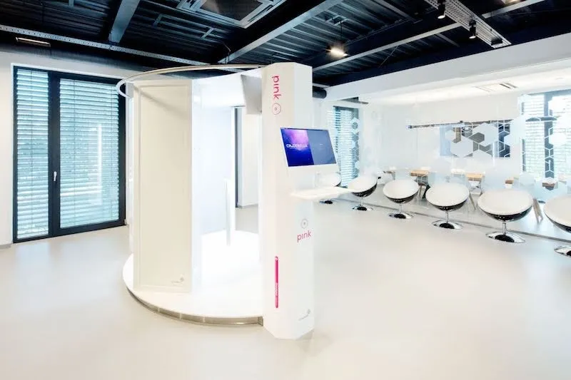
PhotoRobot Medical - PINK에 오신 것을 환영합니다.
PhotoRobot Medical 클리닉 사진 시스템인 PINK를 구매하신 것을 축하드립니다! PhotoRobot PINK는 자동화된 사진 프로세스 분야에서 수십 년간 쌓아온 전문적인 경험과 혁신을 대표할 뿐만 아니라, 클리닉 환경에서 환자의 자동화된 사진 촬영을 지원하도록 설계된 PhotoRobot 기술의 혁명입니다. 다음 정보를 사용하여 귀하와 클리닉 팀이 장치에 익숙해지고 PhotoRobot PINK를 워크플로에 환영할 수 있도록 하십시오.
1. 안전 정보 및 지침
중요: 자체 설치 또는 첫 사용 전에 장치에 제공된 지침 외에 항상 PhotoRobot 안전 정보 및 지침을 참조하십시오. 또한, PhotoRobot 장치의 초기 설치는 항상 공인 PhotoRobot 기관에 의해 수행되어야 합니다. PhotoRobot 설치 권한이 있는 기관은 승인된 유통업체 또는 제조업체 자체의 대표입니다. 제조업체는 장치의 잘못된 설치로 인해 발생하는 부상이나 손상에 대해 책임지지 않습니다.
또한, 작동 전에 PhotoRobot PINK 시스템 사용에 대한 다음 안전 지침을 참조하십시오.
1.1. PhotoRobot PINK의 안전한 기계 사용
PhotoRobot PINK의 안전한 작동을 위해 다음 위험 및 지침을 참고하십시오.
- 부상, 감전, 화재, 화상 또는 기계 손상의 위험이 있습니다.
- 건물 내부에서만 장치를 사용하십시오.
- 인화성 제품이나 인화성 제품에 흠뻑 젖은 물품을 기계 근처나 위에 두지 마십시오.
- 기기가 움직이는 동안에는 어떤 부분도 만지지 마십시오.
- 이 기계는 치료 또는 재활 장치로 사용될 수 없습니다.
- 최대 한 명의 사용자만 기계를 사용할 수 있습니다.
- 부상을 방지하기 위해 속도를 천천히 늘리거나 줄이십시오.
- 옷이 기계에 걸리는 것을 방지하기 위해 사용자의 옷은 너무 헐렁하지 않아야 합니다.
- PLATFORM이 움직일 때는 기계를 방치하지 마십시오.
- 기계를 사용하지 마십시오:
- 고르지 않은 표면에서;
- 직사광선이나 열원 근처에서;
- 습하거나 습한 환경에서;
- 밀폐되거나 공기가 통하지 않거나 가연성 물질이 포함된 공간에서.
- 기계 주변의 여유 공간에는 비상 탈출 구역이 포함되어야 합니다.
- 기계 또는 일부 부품이 손상된 경우, 기계를 작동하지 마십시오.
- 물이 기계 또는 액세서리의 전기 부품에 닿으면 감전 또는 사망의 위험이 있습니다.
- PLATFORM 위에 어떤 물건도 올려놓지 마십시오.
- 이 장치는 산업 환경에서 작동하도록 설계되었습니다.
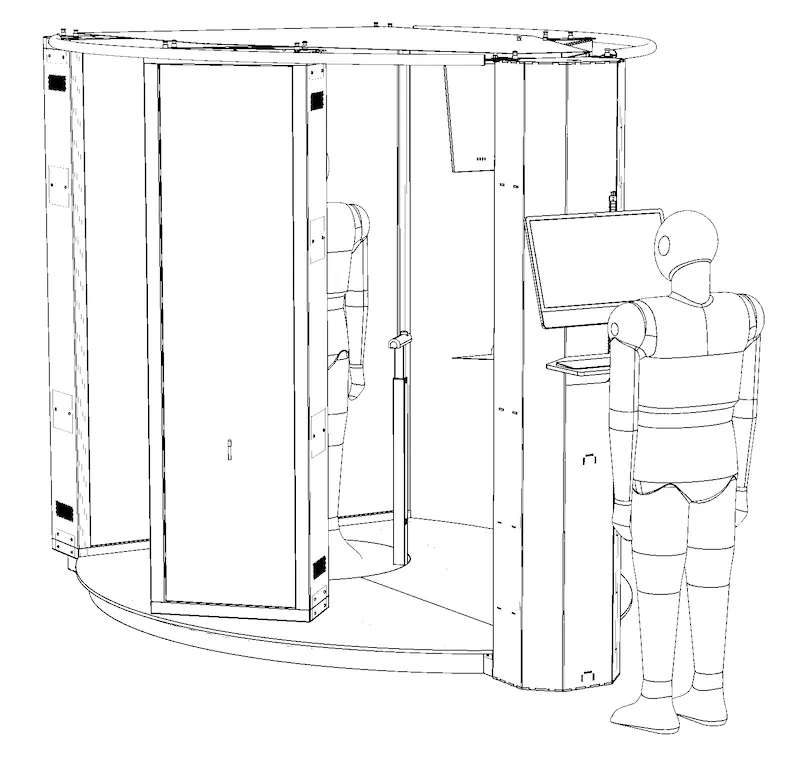
2. 제품 설명 - PhotoRobot PINK
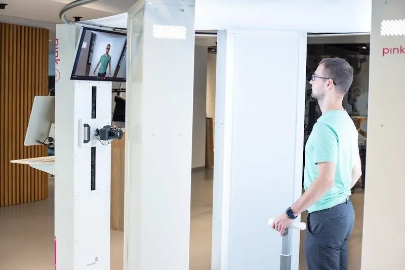
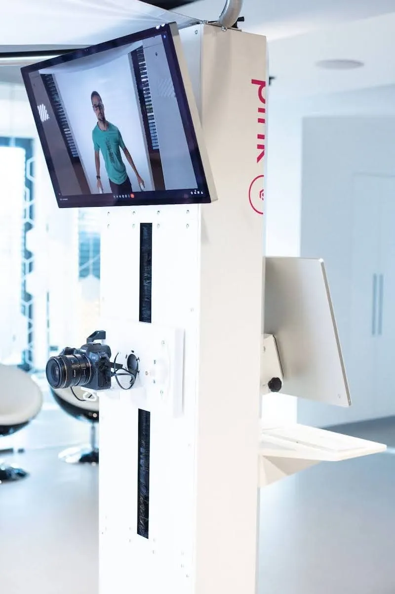
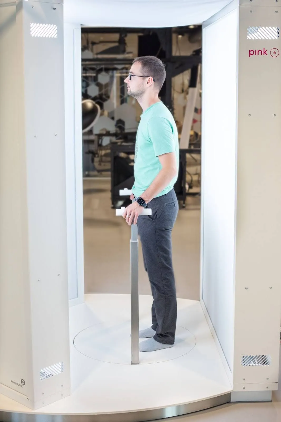
PhotoRobot PINK는 임상 환경에서 서 있는 사람(환자)의 상반신 이미지를 정의된 각도에서 캡처하도록 설계된 기계입니다. 환자는 전문가급 LED 패널을 사용하여 사진 촬영을 위해 조명되며, 균일하게 조명된 배경은 쉬운 자동 배경 분리를 보장합니다. 동시에 모든 조명의 강도는 시스템에 의해 DMX 제어되어, 예를 들어 피부색에 따라 달라질 수 있는 다양한 사전 설정(필요한 경우)을 생성할 수 있습니다.
2.1. 기계 구성 요소
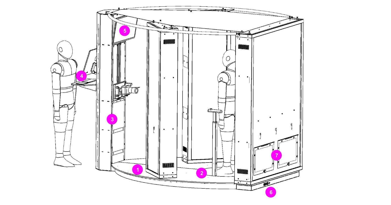
- 기계 바닥 (1)
- 회전 PLATFORM (2)
- 작업자 열 (3)
- 작업자 컴퓨터 (4) – 바코드 스캐너, 키보드, 트랙패드 포함
- 환자 화면 (5) – 카메라 및 스피커 포함
- 전원 소켓, LAN 소켓 (6)
- 서비스 도어 (7)
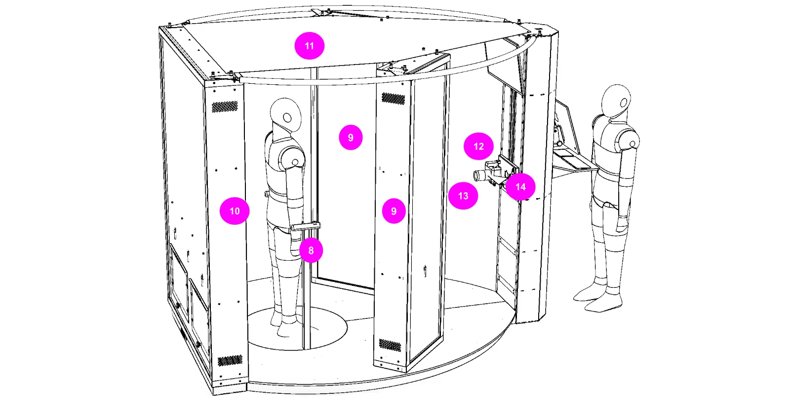
- 환자용 텔레스코픽 핸들바 (8)
- 전면 조명 (9)
- 후면 조명 (10)
- 갓 (11) – 기생광 보호
- 카메라 슬라이더 어셈블리 (12)
- 50mm 고정 초점 렌즈 디지털 카메라 (13)
- 수직 라인 레이저 (14)
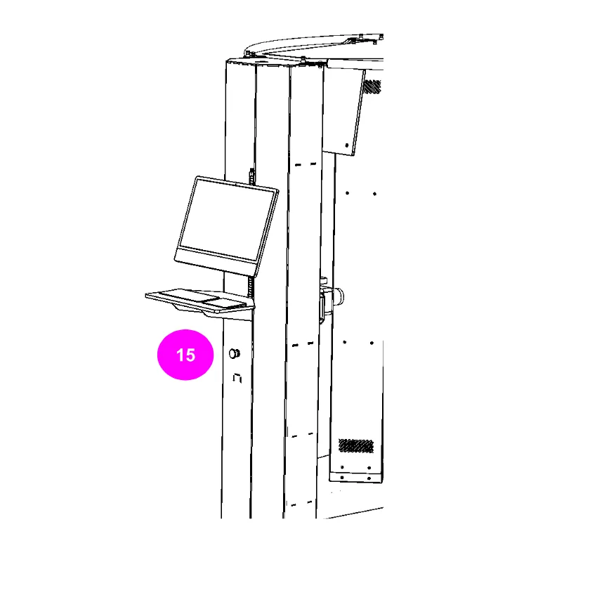
- 비상 정지, 전원 스위치 (15)
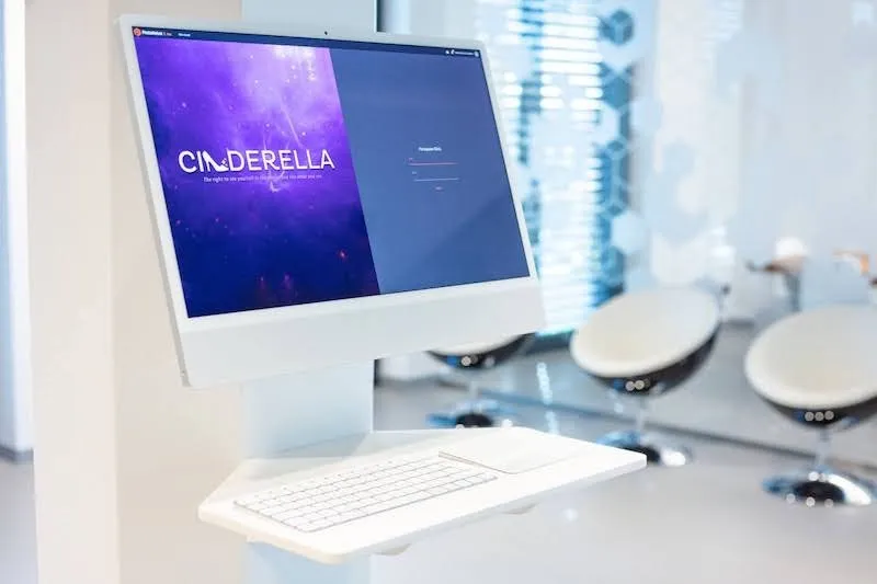
2.2. 작업자 컴퓨터 인터페이스
운영자 작업 공간에는 VESA 마운트 Apple iMac 컴퓨터와 키보드(국가 버전) 및 트랙패드(TABLE에 내장)가 장착되어 있습니다. 동시에 키보드와 트랙패드는 청소를 위해 쉽게 분리할 수 있습니다.
사용자 인터페이스는 PhotoRobot_controls 시스템을 기반으로 하며 두 가지 버전으로 제공됩니다.
- “키오스크” 모드 – 사용자가 환자 바코드를 스캔하는 것만 허용하고, 나머지 프로세스는 완전히 자동화됩니다;
- "전체" 모드 – 전체 시스템에 대한 상세 설정을 허용합니다.
2.3. 환자 컴퓨터 인터페이스
환자 화면에는 VESA 마운트 Apple Studio 디스플레이가 장착되어 있어 의사와의 원격 화상 회의(오디오 및 비디오 사용)가 가능합니다.
- 참고: 동시에 환자 화면은 사진의 자동 캡처 프로세스가 시작되기 전에 환자를 위한 음성 또는 서면 지침이 포함된 일련의 이미지를 표시하는 데 사용될 수도 있습니다.
2.4. 환자 설정
바닥 위 카메라 높이는 환자의 유방에 대한 최적의 위치에 도달하도록 수동으로 조절할 수 있습니다. 렌즈 레벨은 수평 레이저 레벨을 통해 표시되며, 레이저는 자동으로 켜지고 꺼집니다. 기기가 켜져 있고 자동 캡처 프로세스가 실행되지 않을 때는 레이저가 켜져 있습니다. 캡처 프로세스가 시작되면 레이저 라인이 이미지에 나타나지 않도록 레이저가 자동으로 꺼집니다.
환자의 ARM 받침대는 높이 조절이 가능합니다. ARM 위치는 진료소 요구 사항에 따라 결정됩니다. 접이식 망원 지지대를 풀려면 핸들바 상단의 버튼을 누르십시오. 리프트는 공압 피스톤으로 지지되므로 움직임이 느리고 위로 올라가는 방식은 일반적으로 자동입니다. 아래로 이동하려면 (버튼을 누른 상태에서) 아래로 눌러야 합니다.
2.5. 네트워크 연결
로봇에는 필요한 모든 네트워크 구성 요소가 내부에 장착되어 있습니다.
- 컴퓨터 네트워크(내장 라우터)를 통한 컴퓨터 및 로봇 컨트롤러,
- USB를 통한 카메라 (컴퓨터로),
- DMX 버스를 통한 LED 조명 (로봇 컨트롤러로),
- USB를 통한 바코드 리더기 (컴퓨터에 연결).
다음 텍스트는 서비스 및 진단 목적으로만 유용합니다. 기계 작동은 이러한 단계 없이도 원활합니다.
2.5.1. 컴퓨터 네트워크에서 PINK 로봇을 찾으려면 로봇의 전원 스위치가 OFF 위치에 있는지 확인하고 전원 코드를 전기 소켓에 꽂으십시오. 그런 다음 기기를 인터넷에 연결하십시오. 두 커넥터는 기기 뒷면에 있습니다.
2.5.2. 다음으로, 기기의 주 스위치를 켜고 기기가 완전히 작동할 때까지 2분 동안 기다립니다(이렇게 하면 기기 컨트롤러, 조명 컨트롤러 등이 시작됩니다). 나중에 컴퓨터와 확장 디스플레이를 켭니다.
2.5.3. PhotoRobot 계정 다운로드를 통해 로컬 네트워크에서 로봇을 찾는 “Frfind” 유틸리티를 다운로드하고 Frfind 애플리케이션을 시작합니다. 로컬 네트워크에서 PhotoRobot을 검색합니다. 찾으면 해당 IP 주소를 복사하여 컴퓨터에서 시작된 웹 브라우저에 URL 형식으로 붙여넣습니다. 그러면 서비스 GUI가 열립니다.
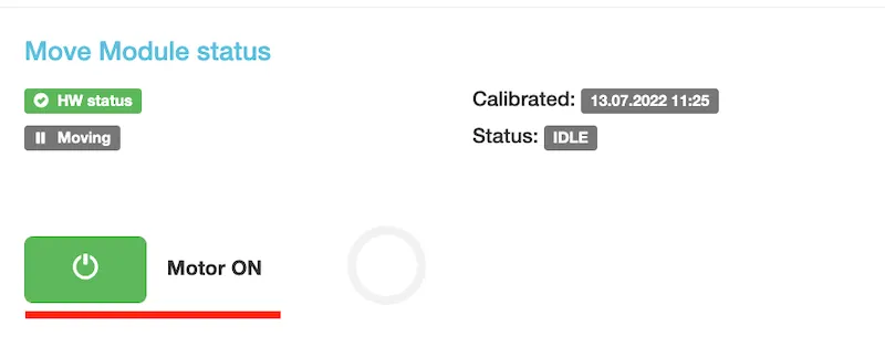
2.5.4. 서비스 GUI에서 모터를 켜십시오.
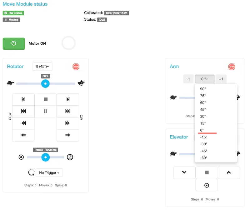
3.5.4. 다음으로, PLATFORM을 아무 각도로 돌려 테스트합니다.
3. 소프트웨어 - PhotoRobot Controls App
작업장 제어는 PINK 로봇 배송의 일부인 PhotoRobot Controls 소프트웨어에 포함되어 있습니다. 소프트웨어 라이선스에 액세스하려면 account.photorobot.com에 등록하십시오 (관련 라이선스 키는 PhotoRobot 지원팀에 문의하십시오).
소프트웨어는 PhotoRobot 계정 다운로드 페이지를 통해 다운로드할 수 있습니다.
PINK 작업 공간에는 작업자가 소프트웨어에 대한 최소한의 지식으로도 쉽게 사진을 찍을 수 있도록 특별히 수정된 소프트웨어가 포함되어 있습니다. 이를 위해 작업자를 스캔 프로세스 전반에 걸쳐 안내하는 마법사가 개발되었습니다.
애플리케이션을 시작하면 마법사 모드가 자동으로 켜집니다.
참고: PhotoRobot 마법사에 대한 자세한 내용은 PhotoRobot Controls - Wizards를 참조하십시오. 마법사 모드에 대한 기술 지침은 마법사 모드 구성 가이드를 참조하십시오.
3.1. PINK 시작 방법
3.1.1. PINK로 사진 촬영을 시작하려면, 사진을 촬영할 프로젝트를 선택하십시오. PINK의 경우, 프로젝트는 전 세계 어딘가의 작업장 위치를 의미할 수 있습니다. 예를 들어, 포르투갈과 같습니다.
3.1.2. 프로젝트를 선택하면 촬영한 환자 목록이 나타납니다. 새로운 사진 시리즈를 찍으려면 목록 상단의 + 사람 추가 버튼을 클릭하여 마법사를 시작하십시오.
3.2. 마법사 단계
3.2.1. 마법사의 첫 번째 단계에서 사진을 찍을 환자를 지정해야 합니다. 익명성을 유지하기 위해 QR 코드/바코드를 작업장의 일부인 무선 코드 리더기와 함께 사용하기로 합의했습니다. 각 환자는 시스템에서 식별될 고유한 QR 코드/바코드를 갖게 됩니다.
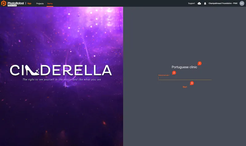
- 사진 스캔 프로젝트 이름 (1)
- 환자 QR / 바코드 (2)
- 확인 및 스캔 시작 (3)
3.2.2. 마법사를 시작하면 다음 화면에서 사용자에게 점진적으로 작업을 요청합니다. 첫 번째 단계에서는 카메라의 LiveView가 자동으로 켜집니다. 동시에 인터페이스의 왼쪽에는 현재 단계와 지침이 표시됩니다. 그런 다음 다음과 같은 주요 사용자 컨트롤이 있습니다.
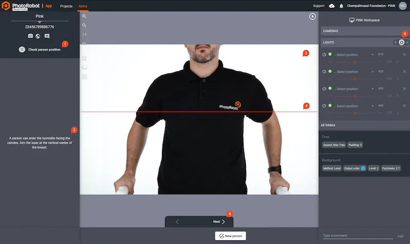
- 단계 이름 (1)
- 단계별 지침 (2)
- 카메라 라이브 뷰 (3)
- 레이저 (4) – 카메라가 부착된 손잡이를 잡고 수직으로도 위치를 조정할 수 있습니다.
- 조명 제어 (5) – 조명 제어를 위한 3단 스위치:
- 달 아이콘: 완전히 끄기
- 작업 아이콘: 스캔 중 감도 표시, 다음 단계에서 스캔을 시작하는 즉시 위치가 자동으로 켜지므로 올바른 위치에 있는지 걱정할 필요가 없습니다.
- 전체 아이콘: 전체 조명 강도
- 다음 버튼 (6) – 지침을 완료한 후 다음 단계로 이동하려면 클릭하십시오.
3.2.3. 다음 단계에서는 환자 스캔 과정이 시작됩니다. 재생 (시작) 버튼을 누르면 작업 공간이 미리 정의된 각도에서 자동으로 사진을 촬영합니다. 그런 다음, 캡처 프로세스가 완료되면 사진이 자동으로 잘리고 파란색 배경이 설정됩니다. 이 단계의 컨트롤은 다음과 같습니다.
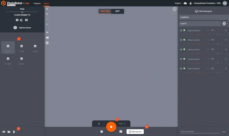
- 환자가 스캔될 사전 설정 각도 (1)
- 재생 버튼 (2)을 눌러 스캔 프로세스를 시작합니다.
- 삭제 버튼 (3)을 눌러 캡처를 반복하고, 기존 이미지를 삭제하고, 재생 버튼을 사용하여 캡처를 다시 시작합니다.
- 스캔에 만족하고 다음 사람 스캔으로 전환하고자 할 때를 위한 새 사람 (4).
이후 다음 사람으로 전환하면 마법사의 첫 번째 단계가 다시 표시되고 사용자는 위에서 설명한 단계를 반복합니다.
3.3. 데이터 구조
데이터 구조 수준은 다음과 같습니다:
프로젝트 > 이미지 유형 > 환자 > 폴더 > 이미지.
샘플 계층 구조는 다음과 같습니다:
- 포르투갈 클리닉 (프로젝트)
- 처리됨 (이미지 유형 - 이 폴더에는 편집/자르기된 최종 이미지가 있습니다)
- 20000001_9000001 (CCC 및 CID 환자) [형식: CCC_CID]
- 2023-01-17 (폴더 - 스캔 배치) [형식: YYYY-MM-DD]
- 20000001_9000001_r000_a000.png (이미지)
[형식: CCC_CID_row_angle.png] - 20000001_9000001_r000_a045.png (이미지)
- …
- 20000001_9000001_r000_a000.png (이미지)
- 2023-02-01 (폴더 - 스캔 배치)
- 20000001_9000001_r000_a000.png (이미지 - 특정 각도)
- 20000001_9000001_r000_a045.png (이미지 - 특정 각도)
- …
- 2023-01-17 (폴더 - 스캔 배치) [형식: YYYY-MM-DD]
- 20000002_ (CID 없는 환자)
- 2022-01-17 (폴더 - 스캔 배치)
- 20000002__r000_a000.png (이미지 - 특정 각도)
- 20000002__r000_a045.png (이미지 - 특정 각도)
- …
- 2022-01-17 (폴더 - 스캔 배치)
- 폴란드 클리닉 (프로젝트)
- 처리됨
- 20000005_9000006 (CCC 및 CID 환자)
- 2022-09-01 (폴더 - 스캔 배치)
- 20000005_9000006_r000_a000.png (이미지)
- 20000005_9000006_r000_a045.png (이미지)
- …
- 2022-09-01 (폴더 - 스캔 배치)
- 20000005_9000006 (CCC 및 CID 환자)
- 처리됨
참고: 샘플 클리닉 프로젝트 데이터(포르투갈 클리닉 프로젝트)가 필요한 경우, 다운로드 링크를 위해 PhotoRobot 담당자에게 문의하십시오.
하드 드라이브에는 두 가지 유형의 이미지 / 이미지 유형이 있습니다:
- 원본: 카메라 이미지
- 처리됨: 다른 편집 작업이 적용된 잘린 이미지.
동기화를 위해 처리된 데이터가 필수적입니다.
스크립트를 구현하는 경우(폴더 구조 모니터링용), PINK 시스템과 데이터를 동기화하는 데 필요한 지연(시간)이 있어야 함을 고려해야 합니다.
중요: 데이터를 변경하지 않을 것이라고 확신하는 시간을 선택하십시오. 이는 때때로 사람을 다시 캡처해야 하는 경우를 위한 것입니다.
로컬 파일 / 폴더 구성
로컬 드라이브의 대상 폴더 구성은 앱에서 다음을 통해 설정됩니다:
설정 > 일반 > 로컬 파일 > 출력 폴더.
파일 이름 구성
파일 이름 구성은 PhotoRobot에서 제공하며 고객이 변경할 수 없습니다. 파일 이름 구성은 다음과 같습니다:
- 스핀 파일 이름:
- 원본
- ${projectName}/Original/${itemName}_${trackingCode}/${folderName}/${itemName}_${trackingCode}_${turnAngle}.jpg
- 처리됨
- ${projectName}/Processed/${itemName}_${trackingCode}/${folderName}/${itemName}_${trackingCode}_${turnAngle}.jpg
- 원본
- 스틸 파일 이름:
- 원본
- ${projectName}/Original/${itemName}_${trackingCode}/${folderName}/${itemName}_${trackingCode}_${turnAngle}.jpg
- 처리됨
- ${projectName}/Processed/${itemName}_${trackingCode}/${folderName}/${itemName}_${trackingCode}_${turnAngle}.jpg
- 원본
마법사 일반 구성
모든 마법사 구성은 PhotoRobot에서 제공합니다. 고객은 이러한 구성을 수정하지 않는 것이 좋습니다.
마법사의 일반 구성은 설정 메뉴 / 마법사를 통해 사용할 수 있으며, 여기에는 다음 설정이 포함됩니다.
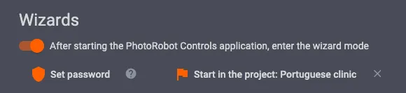
- PhotRobot Controls 애플리케이션을 시작한 후 마법사 모드로 진입
- 프로젝트 시작: 포르투갈 클리닉 – 각 클리닉의 프로젝트는 위치에 따라 다릅니다.
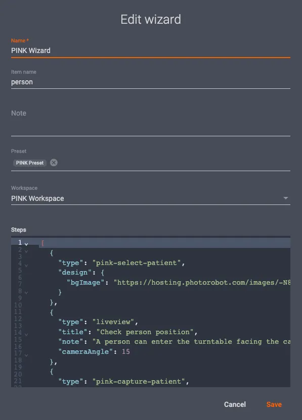
마법사 단계 설정
다음은 모든 PINK 워크스테이션에 대한 일반 단계 설정을 자세히 설명합니다. 구성은 설치 시작 시 한 번 생성됩니다.
구성을 추가하려면 설정으로 이동하여 마법사 옵션을 열고 + 마법사 추가를 클릭하십시오.
그런 다음, 다음 값을 사용하여 대화를 완료하세요:
- 이름: PINK Wizard,
- 항목 이름: 사람,
- 사전 설정: PINK Preset,
- 작업 공간: PINK 작업 공간,
- 단계: 단계의 JSON 구성을 포함합니다.
다음으로, 다음 구성을 사용하십시오:
[
{
"type": "pink-select-patient",
"design": {
"bgImage": "https://hosting.photorobot.com/images/-N83FQcLGsHMXdcYTzhe/-NEGUsIT6MrjA2Hq5LVF/NORMAL/ko5G2B948qAWsuiQ2Gs8xw?w=1920"
}
},
{
"type": "liveview",
"title": "사람 위치 확인",
"note": "사람은 카메라를 향해 턴테이블에 들어갈 수 있습니다. 레이저를 가슴의 수직 중앙에 조준하십시오.",
"cameraAngle": 15
},
{
"type": "pink-capture-patient",
"title": "사람 촬영",
"frames": [
{"swingAbs": 0, "turnAbs": 0},
{"swingAbs": 0, "turnAbs": 45},
{"swingAbs": 0, "turnAbs": 90},
{"swingAbs": 0, "turnAbs": 270},
{"swingAbs": 0, "turnAbs": 315}
]
}
]
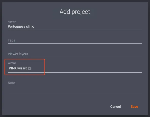
3.4. 새 프로젝트 생성
3.4.1. 새 프로젝트(새 클리닉)로 스캔하려면, 헤더에서 + 프로젝트 추가를 클릭하여 프로젝트 목록에서 새 프로젝트를 생성할 수 있습니다.
3.4.2. 새 프로젝트 추가를 선택하면 프로젝트 이름을 선택할 수 있는 대화 상자가 열립니다.
3.4.3. 다음으로, Wizard 필드를 채우는 것이 중요합니다. 이는 사진 캡처 프로세스에 필요하기 때문입니다. Wizard 필드가 완료되었는지 확인하려면 다음 동일한 대화 상자를 참조하십시오.
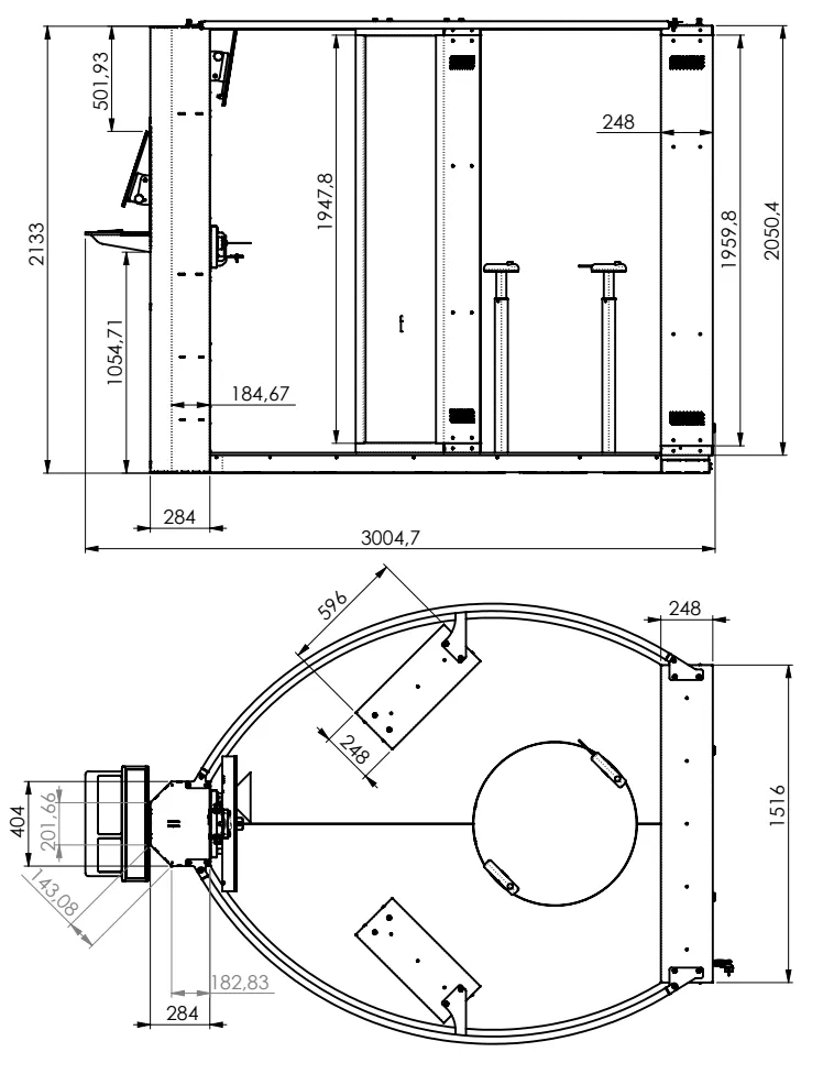
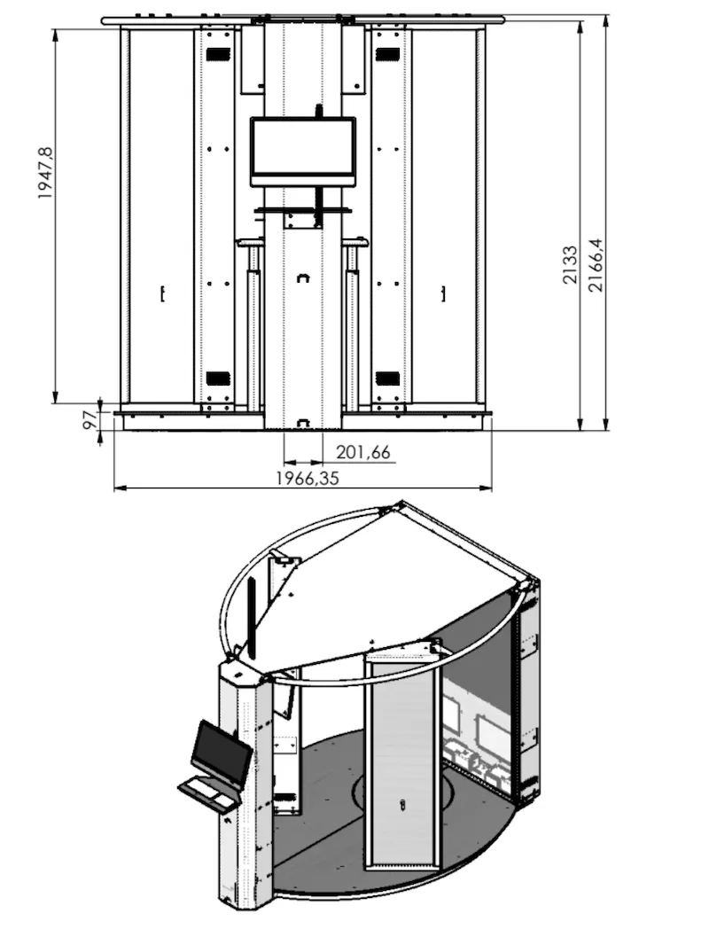
4. 기계 치수
PINK 다이어그램의 모든 치수는 미터법(mm) 측정으로 표시됩니다. 참고: AR 기능이 있는 PINK 기계 치수의 3D 모델을 보려면 다음 바코드를 스캔하고 eDrawingsviewer를 사용하여 3D 모델을 보십시오:

PINK 기계 및 장비의 총 중량은 500kg이며, 치수는 다음과 같습니다.
5. 문제 해결
발생할 수 있는 일반적인 문제에 대한 해결책은 PhotoRobot 문제 해결을 참조하십시오.
기계 작동 중 문제가 발생하면 PhotoRobot 지원팀으로 지원 티켓을 보내주십시오. PhotoRobot의 숙련된 기술팀이 문제 해결을 도와드릴 것입니다.
참고: PhotoRobot 계정 등록은 PINK 장비에서 작동하는 소프트웨어인 PhotoRobot Controls App과 관련이 있습니다.
6. 움직임 정지
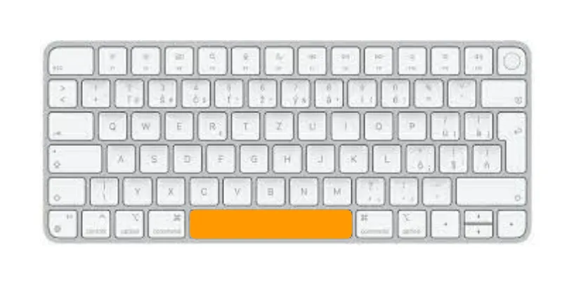
6.1. 소프트 정지
시퀀스가 현재 계획된 움직임을 완료하는 “소프트 스톱”의 경우, 스페이스바를 사용하여 시퀀스를 일시 중지할 수 있습니다.
6.2. 하드 스톱
작동 중(PLATFORM 이동), ESC 키는 즉각적인 “하드 스톱”으로 작동합니다(PLATFORM의 이동 또는 실행 중인 시퀀스를 즉시 중지). 또는 재생/시작 버튼 옆에 있는 정지 버튼을 눌러 이동을 중지할 수 있습니다.

6.3. 비상 정지
하드웨어 비상 정지 버튼을 누르면 움직임이 멈추고(현재 실행 중인 경우) PLATFORM이 자유롭게 움직이게 됩니다(모터 연결 해제). 버튼이 계속 눌려 있으면 기계는 소프트웨어로 움직임을 수행할 수 없습니다.
비상 상황이 해결되고 비상 버튼이 해제된 후, PLATFORM은 초기 위치로 재배치되어야 합니다(다른 위치에 있는 경우) – 자세한 내용은 다음 항목을 참조하십시오.
다음 로봇 움직임은 모터를 다시 켜게 됩니다 (자동 작동 또는 제로 포지셔닝 움직임과 함께).

6.4. Platform을 올바른 영점 위치로 되돌리기
비상 정지 또는 “비제로 위치”에서의 기타 정지 작업 후에는 가상 화살표 키를 사용하여 다음 단계에 따라 PLATFORM을 예상 제로 위치로 이동하십시오.
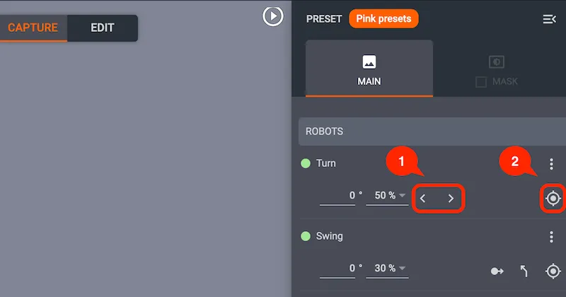
- 1단계: 로봇 위젯의 오른쪽 패널에서 화살표를 사용하여 PLATFORM을 0 위치로 회전시킵니다.
- 2단계: PLATFORM이 0에 있을 때, “현재 위치를 0으로 설정” 버튼을 눌러 이 위치를 확인합니다.
7. 유지보수 및 개정
중요: 기계는 다음과 같이 공인된 직원이 매년 한 번 검토해야 합니다.
- 로터리 PLATFORM 드라이브 검사
- 카메라 리프트 검사
- 텔레스코픽 지지대(핸들바) 검사
- 내장형 LED 패널 및 DMX 컨트롤러의 광도 검사
기술 지원을 받으려면 PhotoRobot 지원 티켓을 생성하십시오 PhotoRobot 계정을 사용하여.


EOS Rebel 시리즈


EOS DSLR 시리즈


EOS M 미러리스 시리즈


PowerShot 시리즈


클로즈업 / 핸드헬드

Canon EOS Rebel 시리즈는 견고한 이미지 품질, 직관적인 컨트롤 및 다양한 기능을 갖춘 초보자용 DSLR 카메라를 제공합니다. 사진 애호가에게 이상적인 이 카메라는 안정적인 자동 초점, 가변 각도 터치스크린, Full HD 또는 4K 비디오 녹화를 제공합니다.
연결
해상도 (MP)
해상도
Canon EOS DSLR 시리즈는 고품질 이미지, 빠른 자동 초점 및 다재다능함을 제공하여 사진 및 비디오 제작 모두에 이상적입니다.
연결
해상도 (MP)
해상도
Canon EOS M 미러리스 시리즈는 컴팩트한 디자인과 DSLR과 같은 성능을 결합합니다. 교체 가능한 렌즈, 빠른 자동 초점 및 고품질 이미지 센서를 특징으로 하는 이 카메라는 이미지 품질을 희생하지 않고 휴대성을 찾는 여행자와 콘텐츠 제작자에게 적합합니다.
연결
해상도 (MP)
해상도
Canon PowerShot 시리즈는 캐주얼 촬영자와 애호가를 위한 작고 사용자 친화적인 카메라를 제공합니다. 간단한 포인트 앤 슛(point-and-shoot)부터 고급 줌 카메라까지 다양한 모델을 통해 편의성, 견고한 화질, 손떨림 보정 및 4K 비디오와 같은 기능을 제공합니다.
연결
해상도 (MP)
해상도
Canon Close-Up & Handheld Cameras는 상세하고 근접한 사진 및 비디오를 위해 설계되었습니다. 컴팩트하고 사용하기 쉬우며 정밀 초점, 고해상도 이미징 및 다양한 매크로 기능을 제공하여 브이로그, 제품 사진 및 창의적인 클로즈업에 적합합니다.


